TECs are inherently reliable due to their solid-state design with no moving parts.
Since TEC failure can result in costly product rejections, high quality and reliability are critical. The expense of system failure far outweighs the cost of the TEC in many cases.
State-of-the-art TECs demonstrate high reliability, often operating for hundreds of thousands of hours. Their Mean Time Before Failure (MTBF) is at least 350,000 hours at room temperature. KIMT’s specialized testing shows even greater reliability, exceeding 1,000,000 hours with a failure rate no more than 50 FIT.
To ensure consistent high performance, KIMT carries out a full range of acceptance and qualification tests.
Acceptance Tests
Acceptance tests verify the quality of each TEC production lot, using either full testing (100% of units) or selective testing (a sample from the lot). Full control removes defective units, while selective control confirms the lot’s overall average quality.
Immediately post-manufacturing, each TEC lot undergoes acceptance testing, including:
- Electrical parameter testing (RAC, Figure-of-Merit, Time Constant t) and polarity testing
- Visual inspection
- Dimensional control
- Temperature cycling endurance testing
Electrical and visual tests are performed on 100% of the TECs in each lot to reject any defective units.
Dimensional and temperature cycling tests are done selectively on a sample (≥10% of the lot). While selective tests do not guarantee complete defect removal, they serve as the basis for lot acceptance. A single failure in a tested sample triggers 100% inspection of the lot, with the rejection of all non-conforming TECs.
Qualification Tests
Qualification tests are conducted to establish or confirm product quality and reliability, and must include:
- Mechanical endurance testing
- Environmental endurance testing
- Operational reliability testing
The Telcordia GR-468-CORE standard provides a qualification testing plan for TEC production.
Qualification Tests Methods
| Mechanical shock |
Mechanical shock testing, performed per MIL-STD-883L, method 2002.5, conditions A/B, evaluates a product’s resilience to single mechanical impacts. During testing, TECs are rigidly mounted and subjected to five impacts in each of six directions (X1, X2, Y1, Y2, Z1, Z2), totaling 30 impacts. The Telcordia GR-468-CORE standard recommends condition A for TECs (500g peak acceleration, 1.0 ms pulse duration). Simulating operating conditions requires an attached mass on the cold side of the TEC. However, more severe condition B can be used as a substitute, per Telcordia GR-468-CORE, if the mass is absent. |
| Vibration |
Vibration testing is performed per MIL-STD-883L, method 2007.3A, to assess a product’s endurance under a variable frequency sweep. During the test, TECs are rigidly mounted and subjected to a swept sine wave vibration, logarithmically varying from 20 to 2,000 Hz. A full sweep (20-2,000-20 Hz) must take ≥4 minutes. This cycle is repeated ≥4 times in X, Y, and Z axes (12 cycles total), with a peak acceleration of 20 g. |
| Shear Strength |
The shear strength test, as defined in MIL-STD-883L, method 2019.10, evaluates a product’s mechanical strength. It measures the maximum shear force a product can withstand before failure or verifies its functionality after exposure to specified forces. For TECs, testing involves an initial shear force of 1.0X, followed by levels of 1.25X and 2.0X. Failure at 1.25X or 2.0X requires microscopic visual inspection to determine the failure mode. |
| High Temperature Storage |
The high-temperature storage test for TECs is mandated by Telcordia GR-468-CORE, without referencing a specific MIL-STD-883L method. This test evaluates TEC endurance at elevated ambient temperatures. The specified conditions are 85°C for 2000 hours. Following the test, TECs must pass visual inspection and acceptance test criteria for serviceability. |
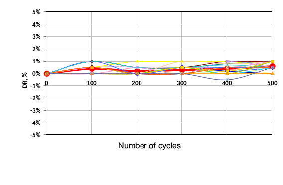
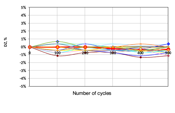
| Temperature Cycling |
These tests, per MIL-STD-883L method 1010, evaluate a product’s endurance to extreme temperatures and rapid transitions. Test samples cycle between separate hot and cold zones in an environmental chamber. Each cycle includes holding at a specific temperature, rapid transfer to the other zone, and subsequent holding at the new temperature. Soak time in each zone must be ≥10 minutes, with a transfer time ≤1 minute. Post-test, TECs must undergo visual inspection and serviceability verification against acceptance criteria. Telcordia GR-468-CORE specifies -40°C for the cold zone and +85°C for the hot zone, with a cycle count of 100 or 500 for TEC qualification. |
| TEC Electrical and Thermal Parameters |
This test verifies that TEC key electrical and thermal parameters—maximum current (Imax), maximum voltage (Umax), maximum cooling capacity (Qmax), and maximum temperature difference (ΔTmax)—match the calculated specifications in the KIMT catalog. |
| Intermittent life |
Telcordia GR-468-CORE mandates a power cycling reliability test for TEC qualification—specifically an intermittent life test—as detailed in MIL-STD-883K, method 1006. This test verifies TEC reliability under cyclic power conditions. The TEC’s hot side temperature is maintained at ≥85°C (maximum long-term operating temperature). During the “On” phase, the TEC is driven at its maximum current (Imax). Each cycle includes a 1.5-minute “On” phase and a 4.5-minute “Off” phase, for a total of 5000 cycles. |
| Lead Integrity |
Tensile strength testing of TEC lead wires is conducted per MIL-STD-883L, method 2004.7, condition D. This test evaluates the connection strength between lead wires and the TEC. A 2.22 N force is applied perpendicularly to the ceramic substrate on the lead wires. The test is failed if a lead wire tears or if any soldered metal junction is detached from the ceramic substrate. |
| Electrical Resistance Insulation |
While not specified by Telcordia GR-468-CORE, insulation resistance testing for TECs is described in MIL-STD-883L, method 1003. This test verifies the electrical insulation between a TEC’s internal circuitry and its external substrate surfaces. During the test, a TEC is connected to a megohmmeter, with one terminal on a TEC electrical terminal, and the other terminal on the heat-absorbing and heat-rejecting surfaces. Applying a ≥100 V DC voltage, the TEC passes if the measured resistance is ≥500 MΩ. |
Sampling Plan
To achieve a high confidence level in TEC reliability during qualification, appropriate sampling is essential. Sample size (SS) calculation utilizes:
- Confidence level
- Lot Tolerance Percent Defective (LTPD)
- Acceptance value (C) – max. allowable rejected units
The Telcordia GR-468-CORE standard specifies these parameters for all test methods, aiding in the calculation of TECs needed for testing. The smallest allowable sample size occurs when using the most stringent acceptance criterion (C = 0).
TEC Failure Criteria
At KIMT, the recommended failure criteria for reliability tests, based on GR-468-CORE and our experience, are:
- ≥5% change in TEC AC Resistance
- ≥5% change in TEC Figure-of-Merit
- TEC operational parameters exceeding specified tolerances